![]() Aero Radio Control
Aero Radio Control
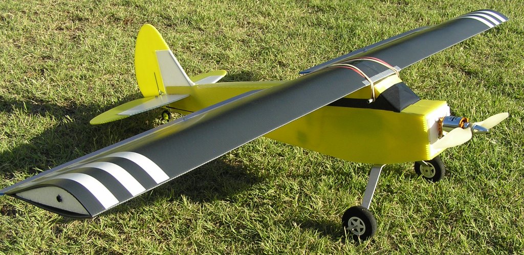
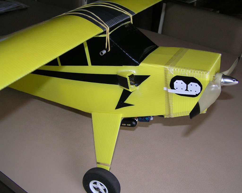
PIPER J3 CUB
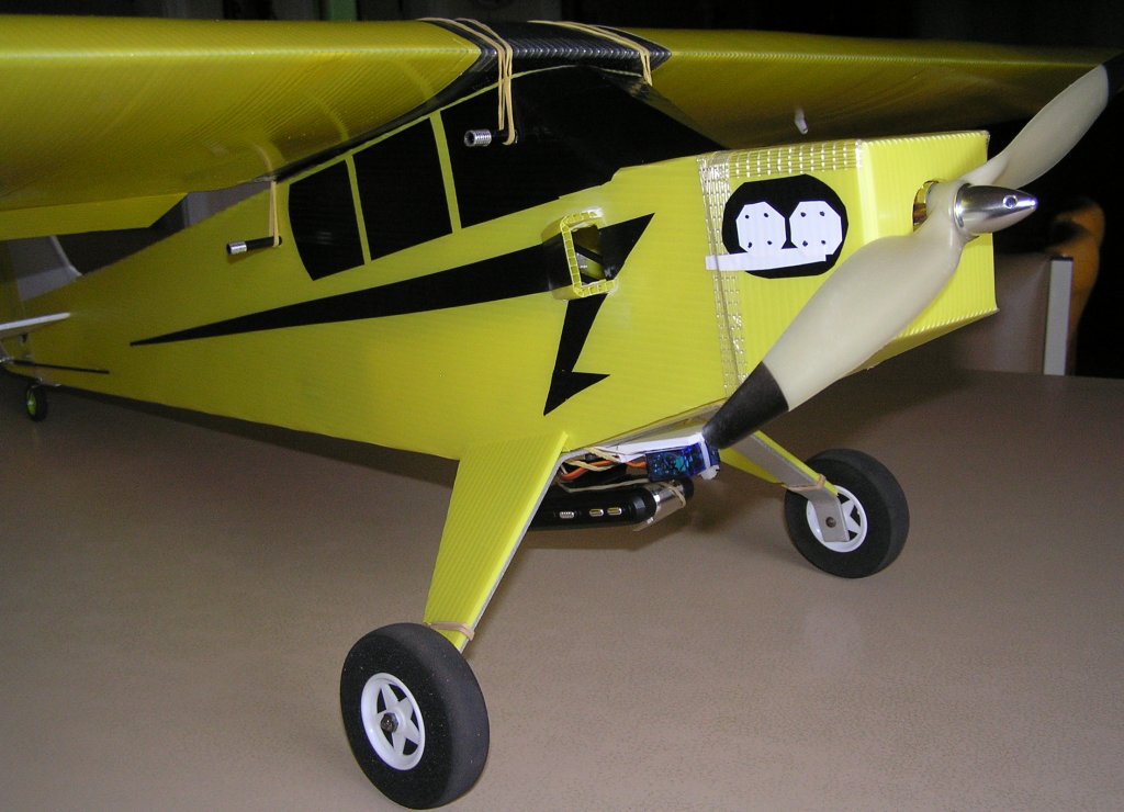
Sporting new Gear skirts, ESC Cooling Scoop and underslung Camera with servo driven Lens.
--== Specifications ==--
Wingspan: 1200mm
Length: 900mm
Weight: 1050g
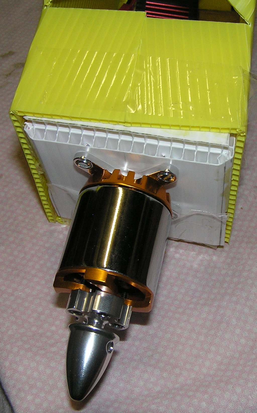
Motor: Turnigy TURNIGY Propdrive D3548 1100kv Brushless Outrunner
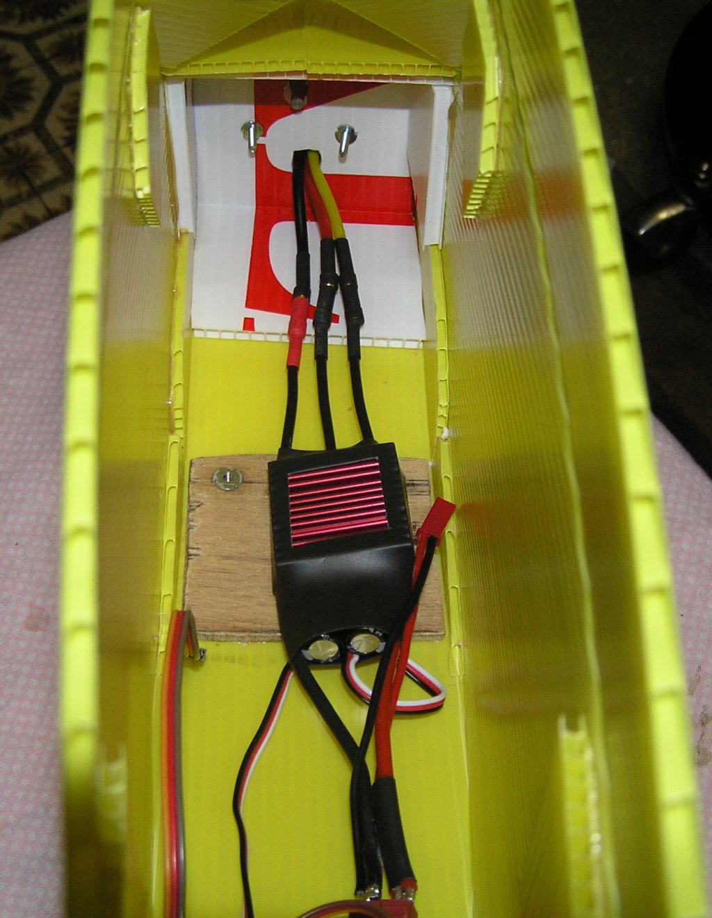
Motor Controller: Hobbyking 50A Brushless ESC
Propeller: APC style 11x5.5E
4 x Servos: TGY-50090M 9g Micro Servo
2 x Wheels: Shock Absorbing D60xH18mm
2 x Axels: 4mm
Tail Wheel: Super Light 5 Spoke Wheel D30x9
Concept PLANS
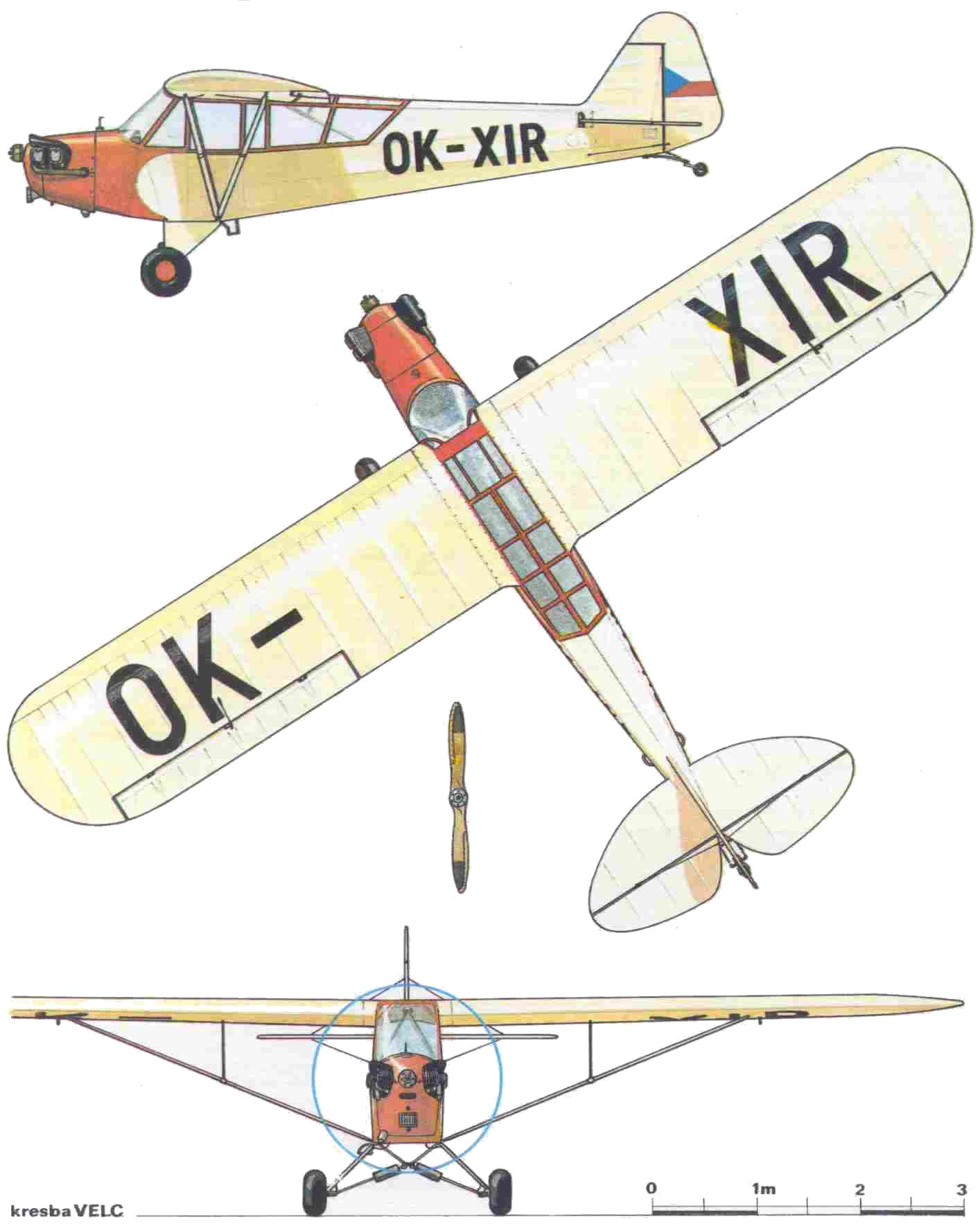
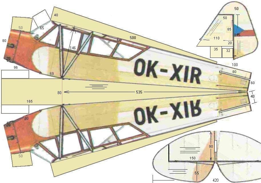
Fuselage Foldout (measurements in mm, not to true scale)
--== Build Log ==--
Rules to Build by:
Rule No. 1 - make the tail as light as you can. You will generally struggle, especially when making a scale-like model with an electric brushless motor, to get enough weight forward of the CoG balance point. Even placing the battery right up against the firewall may not be enough. Adding ballast is an option but it should be a last resort. I used a heavy motor for this build (171grams) and the CoG turned out about right without adding ballast. If you use a lighter motor, you might think about extending the firewall out 20 - 30mm or so. It also means you can beef up the front a bit more, the weight may as well go to strengthening the plane rather than dead weight.Rule No. 2 - make the whole plane as light as you can. Its gotta fly, so this is pretty obvious. Generally balsa models are built very light and fly very well. Corflute models are generally heavier, for the same wingspan, but are as tough as nails, unlike the balsa builds. So I have purposely kept the build simple, but also no unnecessary extras like bulkheads in the fuselage. The CorFlute doesn't need it and it is all added weight. Even go easy on the tape. Don't use 2" wide tape when 1/2" tape will do the job.
Recommended build tools:
1m and 30cm steel rules - these help guide knives to cut clean and straight.
Packing Knife with break-off tips
EXCEL K1 Hobby knife with narrow blade
Plastic Pizza Cutter - this and the 1m steel rule are the secret weapons for making precise "across-the-flute" folds!
Contact Cement - used on trailing edge wing folds and securing tail feathers
Thin CA (Superglue) - only works with graphics grade CorFlute, not industrial grade "black"The build:
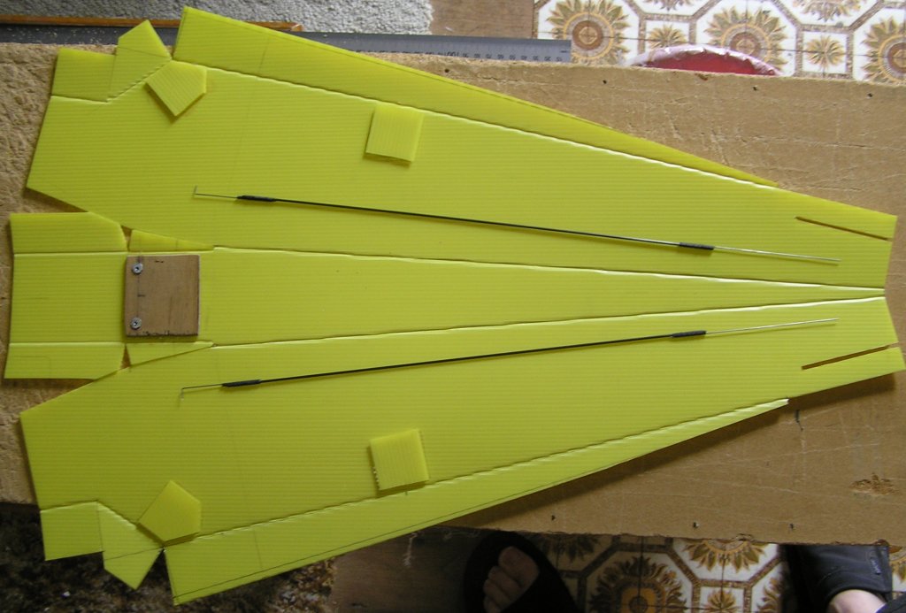
1/ I started with a 800x600x3mm CorFlute sheet graphics grade, which is lighter than the white 3.5mm "Real Estate" sign sheet. (I think 330gsm vs 350) Flute direction running length ways, as seen in the pictures below.2/ I marked a centre line down the middle a flute. This would be the base line for most measurements.
3/ Then I marked out (with a soft 2B pencil) the fold and cut lines as per the plan above.
4/ Using the Packing knife and the 1m steel rule, I cut out the fuse. I left 20mm excess on the top fold section (not shown) so as to make the fold easier to form near the tail.
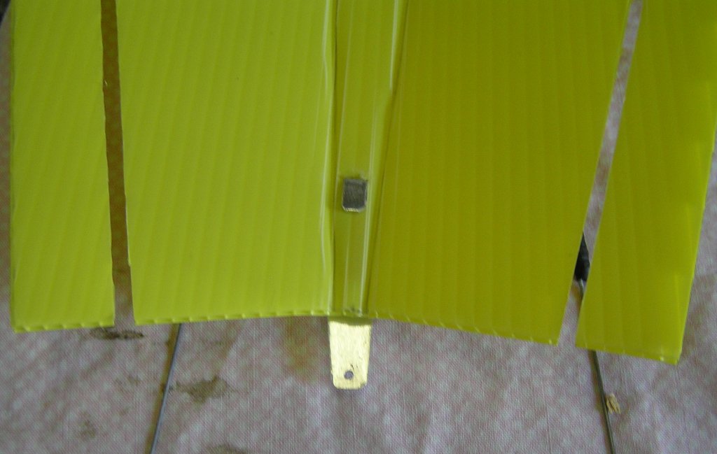
4a/ See this picture below for the cut-out detail around the gear section. I left as much "tab" as available to be used to glue up later to strengthen the nose, gear and firewall area. This was not in the first draft of the plan. Note the forward fold flutes are in one flute from the rearward fold lines and a small cut between the 2 folds
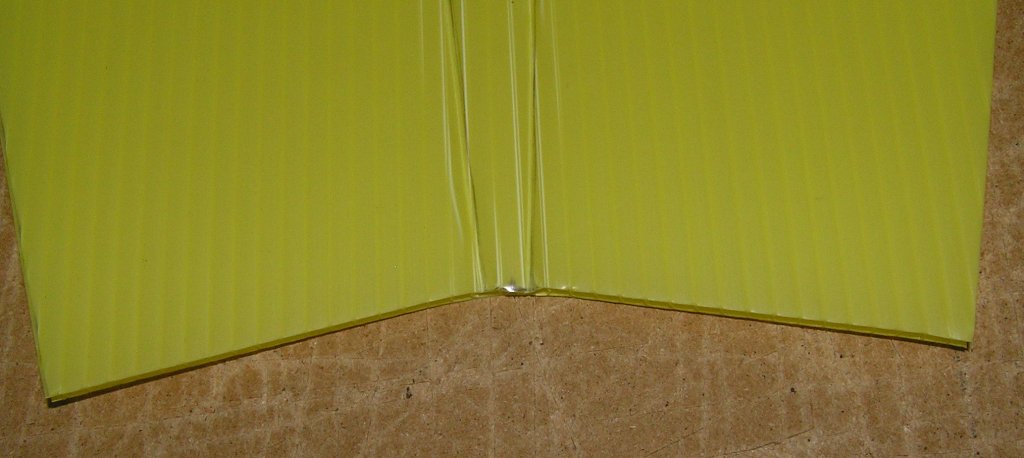
5/ Creasing and folding are next. Using the plastic pizza cutter and the 1m steel rule, I creased the 2 fold lines to the tail. These fold lines should end one flute either side of the centre flute. [Note in the picture below I didn't get it perfect, probably due to running the cutter down the same side of the ruler for both creases. It would have been more accurate to have turned it around and creased with the rule towards the middle for both.] Holding the steel rule near the crease, fold each one to 90 degrees. Then crease the other fold lines, fold them and cut off the excess on the top fold as mentioned earlier.
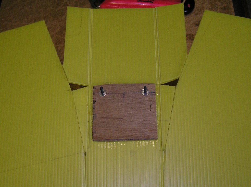
6/ Cut out a 70x55mm piece of (1/8") plywood and glue with contact cement to the fuse 69mm from where the rearward fold terminates, as shown above.
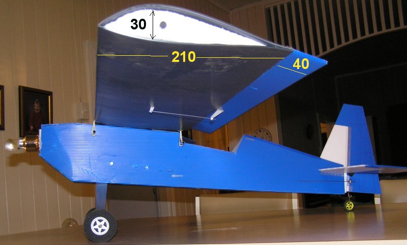
7/ I then glued some off-cuts as reinforcement pads in the position the wing tie down tubes would go. Their position were estimated, but roughly centred 210mm apart.
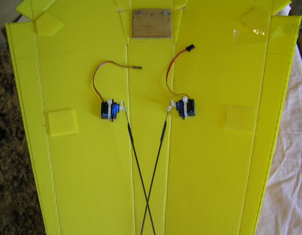
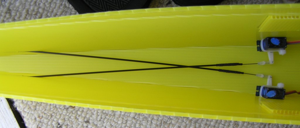
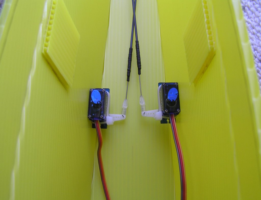
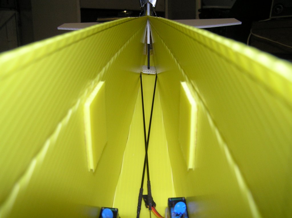
8/ The Rudder & Elevator servos were fitted next. Mount them just forward of the rear wing mount position. I simply made up 2 push rods from some 375 x 1.5mm carbon fibre rod I had, cotton wrapped & CA glued .032" music wire to the ends and positioned then where they were long enough to extent past the tail control points, by estimation. The pictures give the most detail, however the servos have double-sided tape under them to prevent movement, and the zip ties were poked down flutes using the hobby knife to make a small opening and exit slot, not all the way through to the exterior. This results in a neat & secure attachment and the zip ties are not visible on the exterior. I also used GWS horn clips to secure the rod ends to the servos.
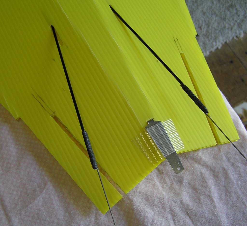
9/ Exit slots were cut in the flute near the tail. Their position was judged by eye to align the rod to where to control horn would be. The slots were about 20mm in length, however the interior slot only overlapped the exterior slot by 2-3mm. This is enough to give free movement of the C/F rod. If you use music wire all the way through, the overlap should become more of an "underlap" due to the smaller diameter.
10/ A tail wheel bracket was cut out of thin aluminium panel plate, with a narrow tab at one end to clamp through the sheet. Leave enough overhang to allow for a hole to line up with the tail piece hinge. I would recommend leaving the drilling of the 1/16" hole until after you have glued the vertical & horizontal stabilisers in place. I was just lucky it all lined up right.
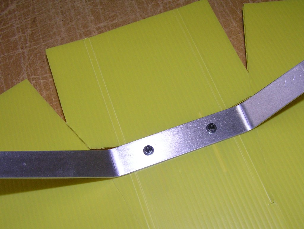
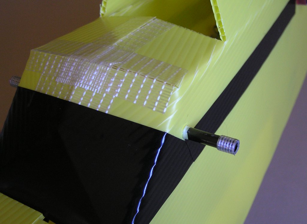
11/ Use your gear strut as a template to mark out the bolt holes. Before fitting them, insert 2 short off-cuts of bamboo skewers into the flutes under where the gear will attach to the fuse. This prevents the flute from crushing when the bolts are tightened. I used blind nuts on the other side, the type with small teeth that bite into the ply. Its almost impossible to access the nuts inside the fuse later so I CA'd them to the ply just to be sure they would not move if the gear was unbolted.
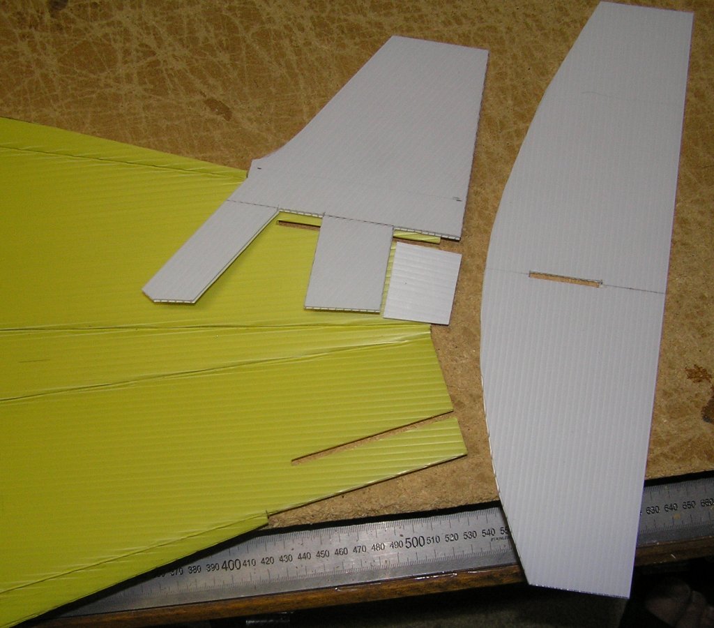
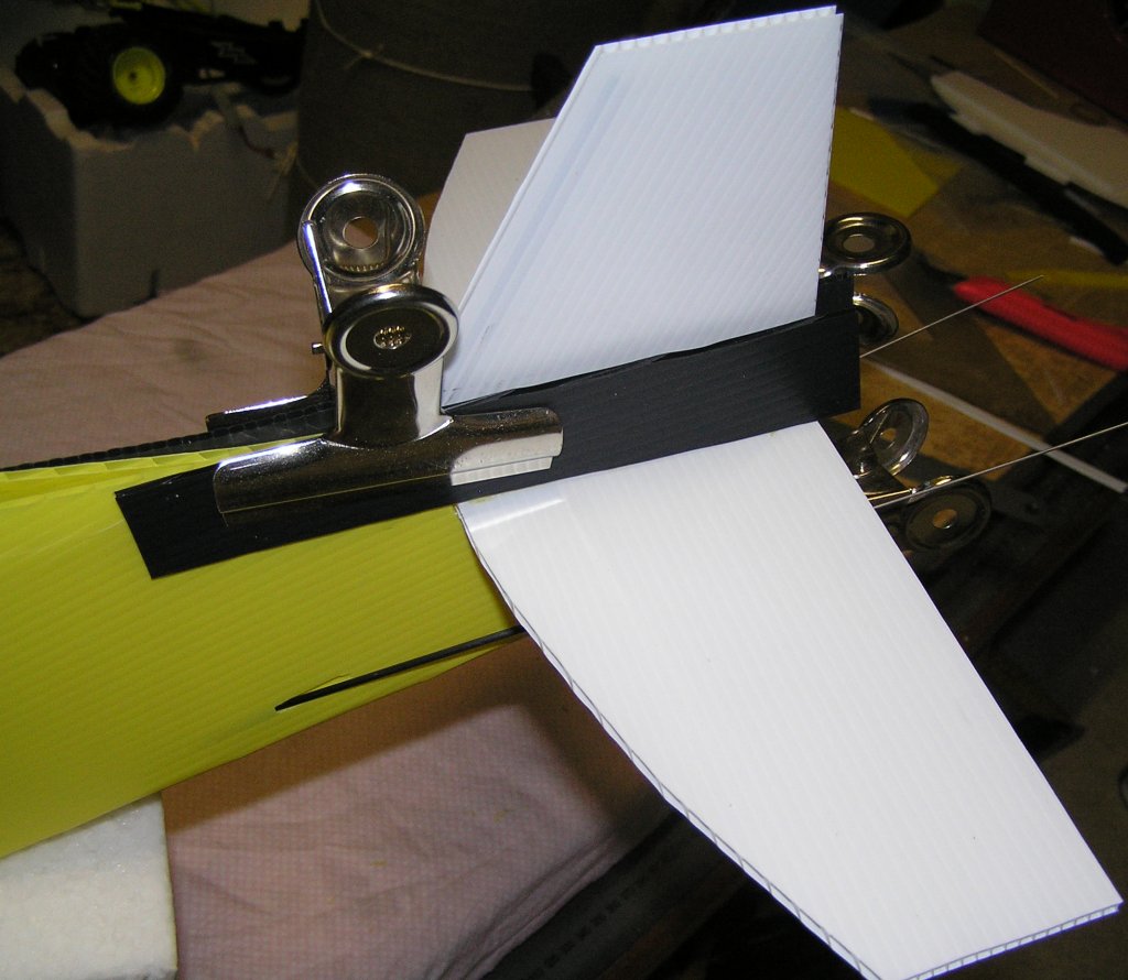
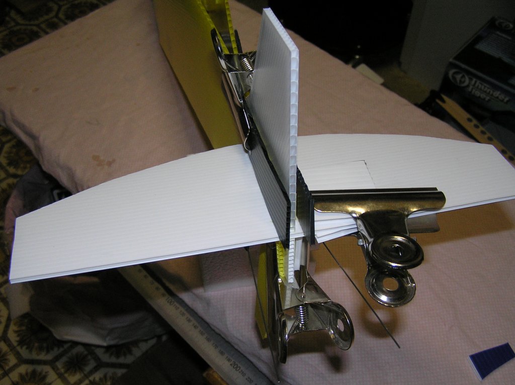
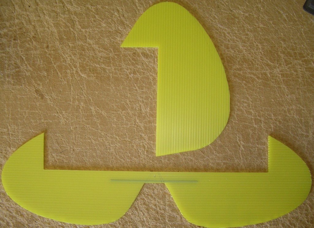
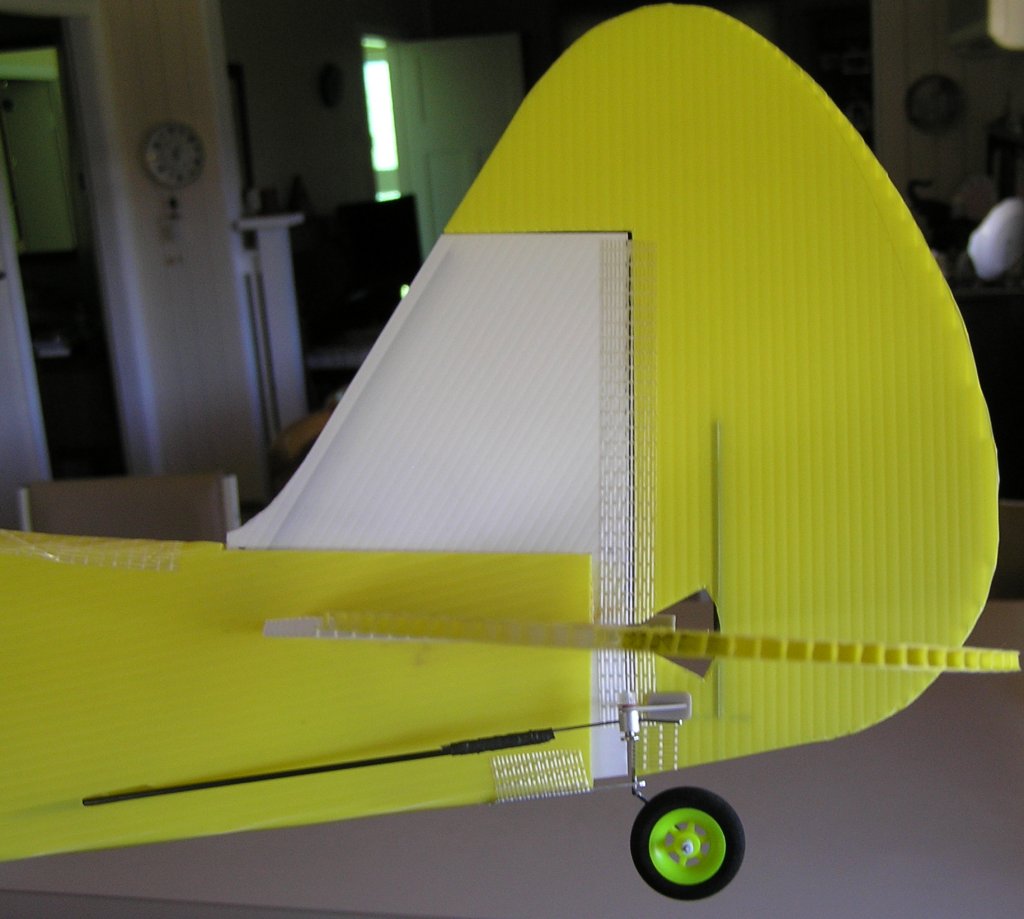
12/ Cut the vertical & horizontal stabilisers from heavier gauge Corflute if you have it. I use the 3.5mm sheet for this as it is less flexible than the 3mm and doesn't add too much extra weight. (see Rule No. 1 - make the tail as light as you can) I departed slightly from my original plan by extending the leading edge into the fuse section. I later trimmed this off and went back to my traditional 3mm carbon fibre down the leading edge flute extending down to a foot that sits wedged near the fuselage floor. This keeps the vertical stab central. See a later photo below for a view of this once glued in. Slot the vert. stab. into the horizontal stab with a close fit. The small square-ish piece forms the lower part of the vert. stab. These all must extend past the rear of the fuse by 10mm to allow for hinge tape, once glued in place.
13/ Cut a small piece of CorFlute to fit between the fuse sides where the leading edge of the vert. stab. extends to. Insert a 3mm carbon fibre tube or BBQ skewer down the leading edge and poke through the small "foot" piece.
Do a few "dry" runs first to get the fitting process down pat. If while doing the dry run you notice the cut-out in the fuse for the horizontal stab as way off square, you may need to do some fine trimming to allow the stab. to sit right.14/ With someone to assist with clamping, apply a thin layer of Contact Cement to all parts that will make contact with each other (ie. both sides). I stress "keep it thin!!" as thick applications take longer to dry and are generally a weaker bond. Also using sparingly means less excess to wipe off and less to mess up the rest of the plane. Coat the fuse first, then the vert stab (but leave the tongue to insert into the horizontal stab without glue). Then apply a thicker dollop right along the cross joint between vert. and horiz. stabs. Lastly do the small square-ish piece and slap it all together. You generally only get one go at joining any two surfaces so do it purposefully. Once its glued together and holding between your fingers, check that the stabs are reasonably square with the rest of the fuselage. If necessary, twist the tail while the glue still gives some movement and clamp once you are satisfied with the result. I used some off-cut Corflute to help prevent clamp marks. Leave overnight or at least 4 hours before continuing.
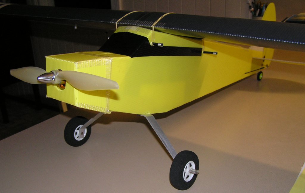
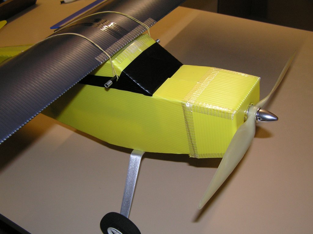
15/ Cut out the firewall from heavy corflute. This is one of the most difficult pieces to form. I used 5mm sheet, however you can use thinner if you reinforce it from behind with ply. I have not given a plan for this as you should tape up the front glue tabs in place and measure what you have. Mine came to 75x75mm. Look at the photo below as see how I have added small off-square angles to the top and bottom fold sections. This is to create a 2-3 degree right facing angle on the firewall to correct motor torque effect. I also cut a sight angle on top of the side tabs to create a small downward facing angle on the firewall to counter a similar thrust issue. Dry fit it and trim until you have it right. Don't be afraid to start a new one and improve on the previous version if its not. Also consider my note on extending the firewall out further if your motor is lighter than the one I used (171g).
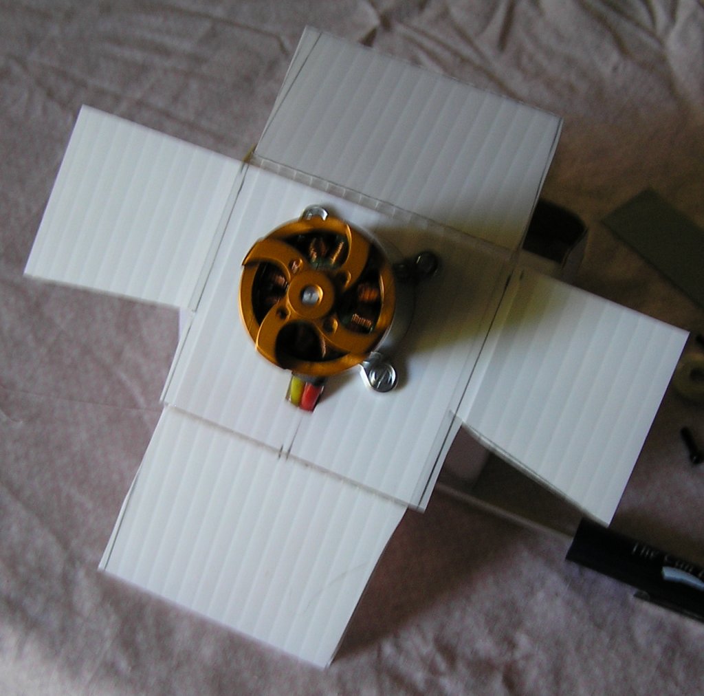
16/ Mount the motor. 5mm sheet is very strong so I didn't worry about using a ply backing plate, like I usually do. The blind nuts seem to offer enough coverage to prevent pull-through, so here's hoping I don't regret that decision. Offset the motor to the left to counter the angle you have put into the firewall tabs. Try to arrange it so that the prop will sit on the centre line of the fuse. Cut holes for the shaft and the wires to traverse. [When I use 3.5mm sheet with Ply, I insert bamboo skewer pieces near the motor bolts to prevent the flute from crushing, although I have only put one on the left side and crushed the right to create the correct thrust angle.]
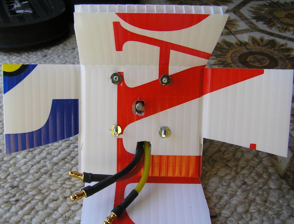
17/ Glue the Fuselage tabs in the front underbelly and the motor mount, with motor fitted and ESC attached. Check you have Rightward and Downward angles as mentioned above. I used tape to hold it all tightly together while drying. Leave at least overnight hours before removing the tape.
18/ Cut-out the tail control surfaces as per the plan. Check measurements against your own horizontal and vertical stabilisers so they are a close fit without interference.
19/ Using 0.062 music wire and a pair of pliers, I bent a short piece to suit the 30x9mm tail wheel I had. Use the pictures below as your guide. The top section is long enough to penetrate the tail 1-2 flutes past where the carbon fibre tube is to be inserted. All are right-angle bends with a 45degree offset in the middle.
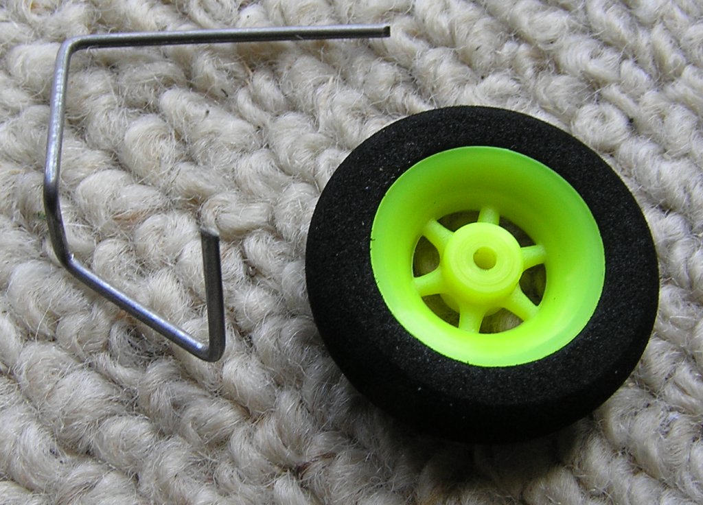
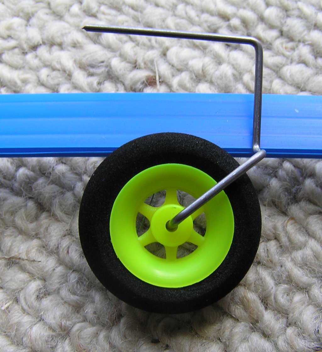
19a/ I glued small plastic tube off-cuts with CA glue to secure the wheel on either side.
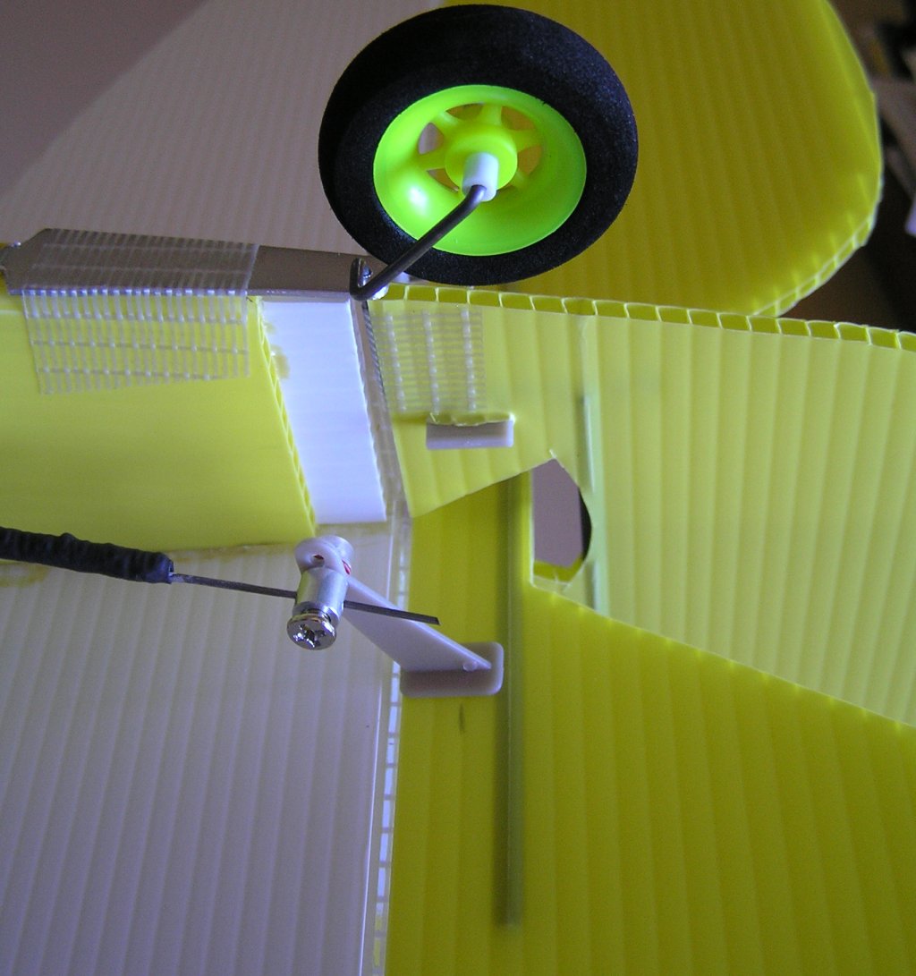
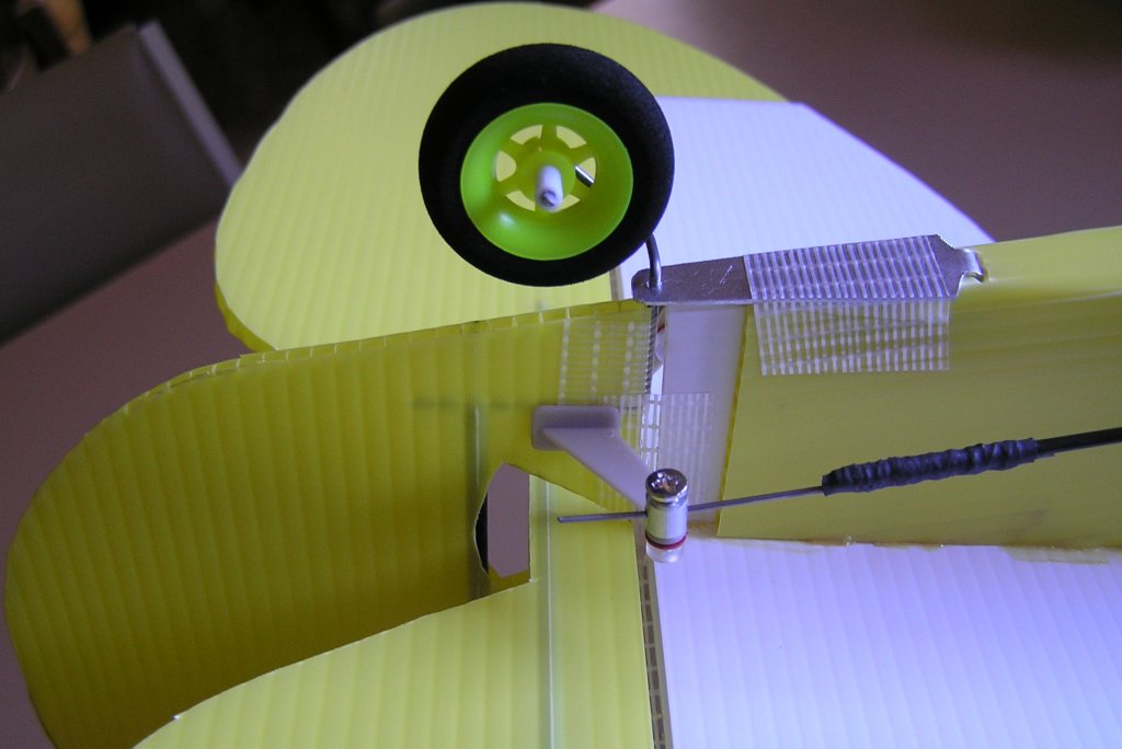
20/ Attach the Elevator first with fibre hinge tape, then mark and cut-out the swing hole in the rudder so that both surfaces can hinge without interference to at least 30degrees from centre. Drill the hole in the tail wheel retainer strap to align with the leading edge of the rudder, about 2mm back from the vertical stabiliser. Pass the wheel wire through the hole and pierce the rudder at a height that will allow the rudder to hinge and a couple of mm of wire to protrude from the strap. ie. the weight of the plane will be transferred to the hinge, not the strap. The strap is there for lateral hold only. Apply tape around the wheel wire, back onto the rudder to hold it in place. Then apply hinge tape to the section of rudder above that point. See the photos for more precise detail.
21/ For the control horns I had, I cut 3 flutes in line with the control rods and inserted them. Later I added some epoxy, rather than use the weak clips that came with them, to hold them securely.
22/ Tape up the cockpit and upper fuselage, all the way back to the tail. I used wide insulation tape to cover the hole in the "windscreen".
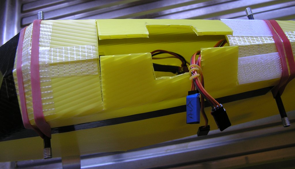
23/ [Its ideal at this point to check the centre of gravity of the plane with all your running gear sitting in place, even if only temporary. If the tail is too heavy you can always move the wing back a bit.] Install the Rubber band posts to match your proposed wing position. I used 6mm carbon fibre tube.
24/ Cut out a battery access hatch and leave a hole for the wing servo cables to protrude. I applied hook & loop strap to help hold the wing in place.
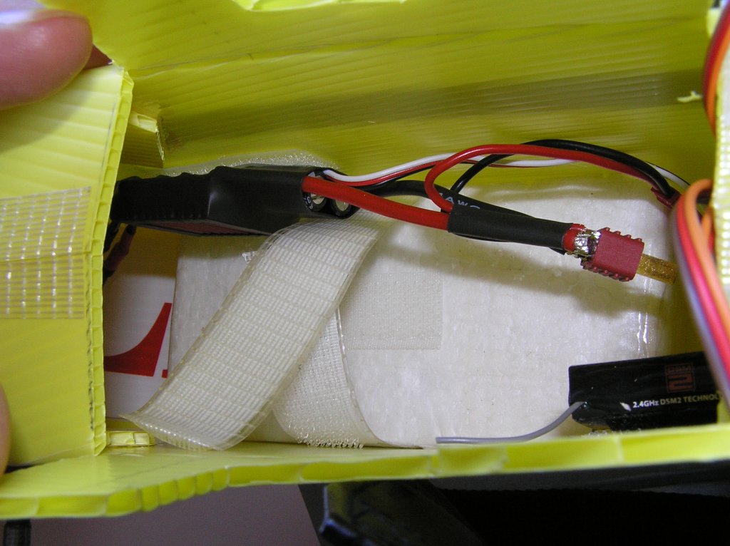
25/ Make a block of foam to sit up against the back of the firewall to prevent battery damage in the event of a crash. Fashion a battery carrier out of EPS foam to sit up against the block at the firewall. I simply taped it in place and made up a battery strap out of hook and loop and fibre tape.
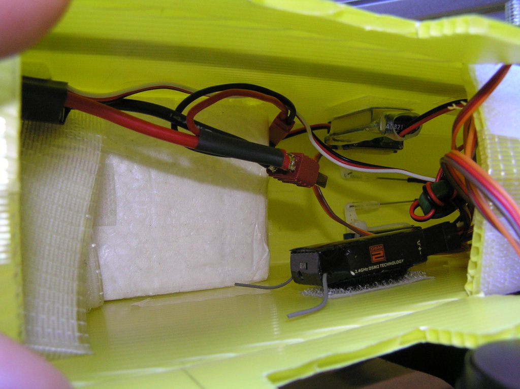
26/ Fit out your electrical/radio gear. I used a separate voltage regulator to ensure a reliable supply to the RX.
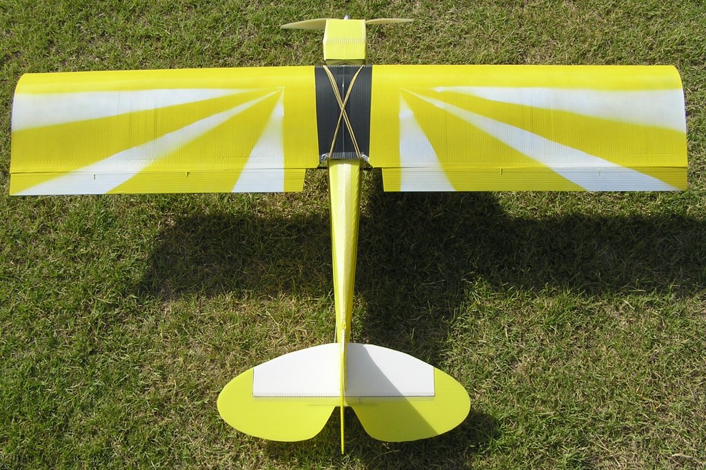
27/ Wing build.
Experimental High Wing Design from CorFlute mounted on an old Fuselage
High-Lift non-symmetrical design using EPS formers. 10mm/8mm C/F Tube spar.
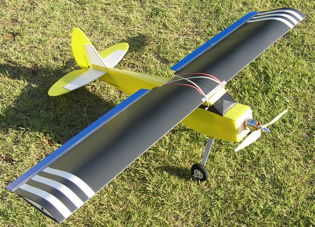
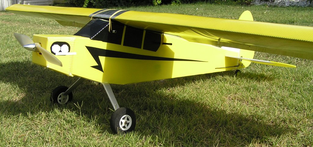
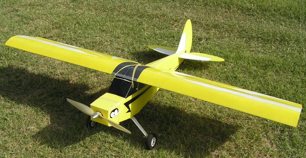
Ready for a test flight. No Cowl as yet.
2020 Update: Most items can now be sourced from Hobbyking's Australian Warehouse.
This is where I got my Corflute from
Another Brisbane shop where I actually do buy my props. He’s generally got everything in stock (unlike a lot of others) and specialises in the small stuff for electric planes.
A 10x5 or 11x5.5 APC from here at $6
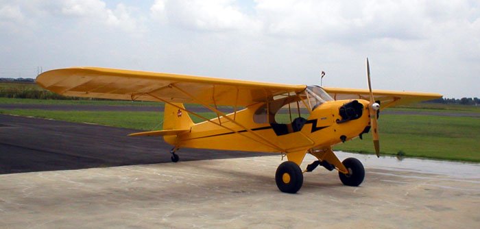
A real Piper J3 Cub
---======---
page updated 15-Mar-2020
back to BLIS ARC